Monday, October 26, 2015

When we last left off, the frame was welded and that was the end of the weekend.

This week, I had a little roadtrip that took much of the weekend away.  However, progress is still being made.

On a slight aside, I managed to find a lathe locally to supplement the shop.  I've been looking for just the right one for quite some time and mananged to get lucky.  I am supposed to pick it up tomorrow, and if I can get it back together in time it will be useful for the upcoming axles.

The frame has been primed and painted.  A number of coats of black gloss in between minor episodes of rain this week, plus a few days to cure to allow handling.  Nothing worse than sticky Rustoleum.

Additionally, I finished the extra bits of frame for the front bearings and painted them as well.

The bearings were loosely mounted, and here is the trick to getting them aligned properly.  I use a long shaft that goes through both sides.  This aligns them all to a common center.  By adjusting and measuring the shaft to the frame, it can also be squared up to the frame as well.  Tighten everything up and slip the shaft out, presto.  In some cases various tolerances made it slightly difficult to pull the shaft out, but not impossible.

In the photo above, the left (front) bearings are being aligned.  The middle and right (rear) are done and tight.  In each of these, the rough cut 3/4" axle stubs are inserted.

The axle stubs will be trimmed to length, faced off, crossdrilled for wheel retention and keyed ( slots ) for the chain sprockets.  The keyway will be 3/16" to match.

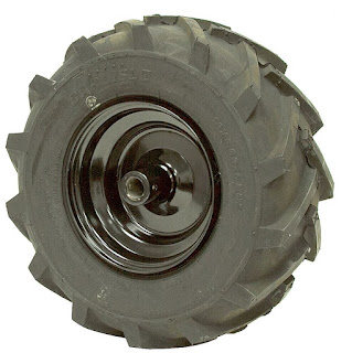
Flipping the frame over and slipping the wheels on allows for a better visual of the final goal:

This allows for the sprockets to be fitted and the roller chain cut to length.  Since I don't have a link breaker, I carefully cut one side link and bent the link to free it from its pins.  This made for a clean break, quick and easy.

Adding the masterlink allowed a test fit of the sprockets that connect the axles together.

Motor mount brackets will be designed and fabbed to fit.  The goal is to allow adjustment front to back for tension and side to side for alignment of the sprockets.

Sunday, October 18, 2015

Frame Welding

Cold today, no rain, but damn it's like 40 outside.

From last night, took the frame and set it up flat on the floor to check the dimensions.  Each corner and joint was made flush and the bolts were lightly tightened.  Check and adjust the diagonals to 47.5" ( the design is 47.5041" - close enough? ).  Adjust the rear inner rails to 2.45" inside to inside edges.  Tighten everything down snug, recheck.  Added a diagonal piece of angle with a couple of clamps to hold it square.  Check again.


Changed the wire on the welder from 0.023" to 0.030" so I can get some penetration.  I think the last thing I welded was sheet metal.

Take everything outside to avoid sparks creating unplanned emergencies and check the measurements one last time.


Remove the clamps and bolts, presto.  The front crossmember is still bolted.  The design allows for easier service of the mower and engine by removing this if necessary.

The welds had decent depth and look OK.


Checking the measurements and flatness - dead on!  When welding, I spread them around a bit so as not to heat one area too much.  I've turned things like this into potato chips before.  This way seemed to work pretty well.  Probably didn't hurt that it was well clamped and bolted.

I'm going to think about whether I want to weld the battery shelf in or bolt it, then I'll paint this to keep it from rusting.  Probably another day, it's supposed to warm up a bit later this week.  It is better to let the paint dry outside, it keeps the peace in my house.

Saturday, October 17, 2015

Frame Start

Rainy and cold today, good day to work inside...

Finished cutting to rough lengths, clean up the ends and drill holes in the frame tubing.


Mockup the gears to check the spacing in the design.  Much easier to change now rather than after welding.

Loosely assemble the frame.

Tomorrow, will check it over against the drawing and possibly finish it.
Drive Basics

Actually, I have been thinking about this for over a year, but only recently started to put a serious effort towards it.  I had originally wanted a tracked version, but exhausted finding a cost effective source for tracks.  Some folks have made their own by machining thick rubber strips and gluing them together.  I really didn't think this would stand the abuse of rough terrain.  Someone suggested using V Belts with cleats, but that might be too aggressive.  I'm still looking.

So, back to the 6x6 idea.  What really triggered the whole project is the availability of certain key parts, namely wheels and motors.  Tires are expensive, times 6 and you get the idea.  Wheelchair motors are also expensive, but EBay is the solution there.

Tires - I came across some nice Carlise Super Lug 13x5.00-6 tires at Surplus Center for $32.95 a pair.  They have a 3/4 bore hub.  There are also individual ones for slightly less with a 1 inch hub, but I didn't want axles that big, nor do I want to sleeve/adapt them.


Motors - Searching EBay and reading a lot about wheelchair motors yielded a pair of Sunrise Medical S525 motors:


They aren't "perfect" but the price was right.  Finding specs for these things is nearly impossible as they are typically customized for each manufacturer.  These are ElectroCraft 24V DC brush motors into a roughly 18:1 right angle gear box.  The shafts (after removing the hubs) are tapered, but I can deal with that.  Ideally a straight shaft is easier to deal with, but again - price.  These things are heavy.

Many different chair manufacturers use different diameter wheels, spec different speeds and weight capacity.  I chose a taller gear ratio 18:1 for a faster shaft speed so I could then gear it down myself.  This minimizes the torque load on the motor itself, and thus the current.  If I had a slower motor, the final drive could be closer to 1:1, but the gearbox torque specs are relatively constant no matter what the ratio, so to avoid running into that it seemed best to go this way.

A quick set of Excel calculations of total weight, desired speed, angle of climb, etc. yielded a set of guidelines for maximum torque required as well as the tractive torque that can be delivered to the ground at each wheel.  It doesn't do any good if you need a ton of torque, can supply it, but the wheels spin and just dig in.

From this evolved a design.  The goals are:
  • 6 wheel drive
  • Tank type steering
  • 24 VDC drive system
  • Gas powered 22 inch mower, adjustable height up to 6 inches
  • Radio Control ( with throttle cut safeties )
  • optional additional channels for additional functions and maybe telemetry
  • optional alternator to charge drive batteries

Below is a snapshot of the CAD design ( I use AutoCAD ).


This helped to guide drive design and bearing selection.

Roller chain is straighforward.  17 tooth drive sprocket, 60 tooth driven sprocket, 20 tooth wheel to wheel connecting sprockets.  I sometimes call them gears, but I mean sprockets.

Bearings are 3/4 inch bore pillow blocks.  They are relatively mounting insensitive and are greasable/sealed units.  I toyed with the idea of discrete bearings, but the mounting is important and the ability to grease them is too.

Again, a great source for all of this is Surplus Center.  I ordered all the bearings, sprockets, chain and master links from them.  They are the cheapest I could find, and the quality is decent.  The bearing blocks were about $5.60 or so, compare to $30 to $75 elsewhere.

The frame is 1x1 inch steel tubing, and the axles are 3/4 inch cold rolled steel.  I purchase my steel from Klein Steel Direct in Rochester, NY.  Typical prices are about 70 cents per pound.  24 feet of tube and 6 foot of shaft cost about $28.

I'm cutting the steel roughly to length with a recip saw, then cleaning up the ends separately.


TTFN

Friday, October 16, 2015

A Mower Project?  Why not?

As if you can't tell, from the last post on my other blog ( 2012 ) and my nearly complete lack of presence on other media.  ( yes, I've been on facebook since 2008, but with what like 3 posts maybe ) I don't do this a lot - be patient.

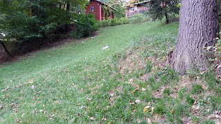
I have a section of really steep hill that I've planted grass on and like to keep mowed.  It used to be a collection of brambles, rocks and poison ivy, but finally cleaned it up a few years ago.


I used a string trimmer for a while, but afterwards it's like I've been running a food processor with the lid off.  I had grass and other odds and ends all over me.

I created the "4x4 Mower" which really isn't 4x4 or any drive at all, but it has cool wheels.


The idea is that it rolls easily over bumps and small holes, allows for a higher cut height, and mainly I don't get green stuff all over me.  The wheels are from Tractor Supply.  The axle diameter is identical, but I had to create extensions on the lathe to allow for the wider wheels, essentially threaded stand offs.  The mower has a new cut height of 5 inches.  The mower is a side of the road rescue unit.  It is on its third engine now.  I don't think the lubrication works well at steep angles ( more on that topic later ).

The hill is steep enough that it is best (read safe) to cut across it, back and forth, top to bottom.  It is tough on the ankles, but doable.  It is easily 45 degrees at some points, maybe more.

I've read about commercially available steep slope mowers, but they are many thousands of dollars.  Places like EvaTech and the now defunct (?) Summit Mowers have some examples.  A few robotic enterprises have also built or can build various versions to suit your wallet, eg. SuperDroidRobotics.

The pictures are detailed enough to get a general idea of what they did.  It seems simple enough.  A frame, wheels, electric motors, radio control, drive mechanism, and a gas powered mower deck.  How hard can this be?

I really like the rubber tracked versions, but treads are about $600 a pair.  Maybe I could find a used pair, but drive is also pretty involved.  Maybe Gen 2.

Enter the 6x6...  a 4x4 is slightly easier, but the wheelbase would end up rather long and the possibility of high centering or scalping the grass is very high.  6 wheels makes more sense with minimal added complexity.

Off to think on this some more...